Bent Shaft Straightening
A bent shaft can occur as a result of damage during shipment, rigging, or operation. Shaft straightening methods, when properly applied, can sometimes be used to salvage damaged shafting.
Because of the different variables involved, shaft bend correction can be as much an art as a science. Each application is unique, and needs to be reviewed on a case-by-case basis.
Table of Contents:
What is the definition of bent shafting?
In a perfectly straight shaft, the centers of each shaft cross-section from end-to-end of the shaft lie on a straight line. A shaft is bent if that is not the case.
In a bent shaft, the axis of the shaft is different than its axis of rotation. The range of the orbit or gyration caused by the shaft bend is defined as the shaft runout, and is typically measured in terms of "TIR" (Total Indicator Reading).
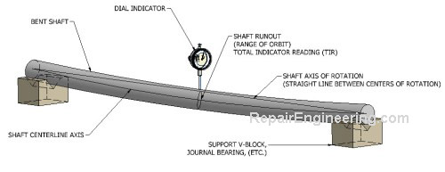
What are the consequences of operating a piece of equipment with a bent shaft? There are several, including...
- Shaft misalignment
- Equipment vibration due to unbalance
- Damage to bearings, seals, and couplings
- Contact, and possible seizure with, close-clearance surfaces
- Material fatigue
What causes shafts to bend? A bent shaft can be caused by one or more of the following factors...
Mechanical overload:
- Damage during rigging or improper handling
- Impact during operation
- Machine misalignment
- Unequal machining operations
- Vibration during shipment
- Improper material handling during heat-treating, rolling, forging, thermal stress relieving
- Elevated temperature during operation
A shaft that is initially straight can bend due to stresses caused by heavy shrink fits with mating components such as a turbine wheel, for example.
Bent shafts caused by assembly stack-up stresses are usually not correctable by simply straightening the shaft itself. The assembly needs to be analyzed as a complete unit, and corrected accordingly. Sometimes, a change in the fits between the shaft and its mating components is required to accomplish the straightness needed.
What is the best bent shaft straightening method?
Unfortunately, there are no simple answers to this question. A successful shaft straightening repair is dependent on several interrelated variables, with the result that a method that is successful in one case may be unsuited for another.
In general, it is safe to say that the best method is the one that requires the fewest corrections to achieve the desired straightness tolerance, that adds the least additional stress to the shaft.
It is desirable to attempt to make the fewest adjustments possible in order to achieve the desired result. The more times that a shaft is deflected, the higher the likelihood that the induced stresses in the material will cause more problems than they solve.
In an ideal bent shaft straightening process, the repair relaxes the stresses in the material fibers that initially caused the shaft to bend. If the process restores the deformed shaft material fibers to their original state, prior to bending, the chances for a long-term successful outcome are good. However, this can be difficult to accomplish in practice.
In practice, the bent shaft straightening process sometimes simply creates additional stresses in the material that oppose the material stresses that caused the initial bending. As a result, the shaft material fibers that initially caused the shaft to bend remain in a stressed condition after the repair is complete
A shaft straightened in this manner can initially indicate straight. However, the long-term success of the "balanced stresses" is doubtful and unpredictable, as those material stresses can relax over time.
To determine an appropriate approach for a particular application, it is helpful to review and evaluate the factors discussed in the next section.
What factors determine the feasibility of a successful bent shaft straightening repair?
With the urgency of an equipment downtime situation, it can be tempting to begin a repair process without fully understanding the problem or considering the consequences of the proposed correction. However, it is worth taking a few minutes to properly assess the situation to determine if the selected course of action is appropriate.
It is important to have a clear understanding of the problem prior to starting, and to not get in a hurry when correcting shaft straightness.
A successful bent shaft straightening repair can sometimes be a labor-intensive activity that can require several iterations to achieve the desired result.
Some of the criteria that determine the outcome of a bent shaft straightening project include...
Cause of the bend
To determine the feasibility of successfully straightening a bent shaft, and to select an appropriate repair method, it is important to understand why it failed initially.
Shafts that are bent as a result of a mechanical overload condition are generally easier to diagnose and straighten than other types of bends. They also can have a higher probability of permanent success.
However, if a bent shaft is the result of unequal relaxation of internal stresses within the shaft itself, the straightening process can be very time consuming. Due to internal shaft stresses, a procedure performed at one spot can sometimes cause an unexpected bend to occur at a different location. Because of the unpredictable characteristic of the internal stresses, straightening such shafts can be temporary with uncertain long-term results.
Type of bend
The success of a bent shaft straightening project is dependent on the type of bending that needs to be corrected. For example, a shaft that has a deflection at a single location is easier to repair than a shaft with multiple bends, or one that has a gradual distortion over its entire length. The most difficult types of bends to straighten are those that have a combination of bending and twisting.
A bent shaft survey map is used to determine the type of bending that needs to be straightened.
Shaft material
The material from which a shaft is manufactured is a significant factor in determining the feasibility of a successful repair. Some materials are inherently more stable than others, and are therefore less susceptable to distortion. Those same materials tend to be more forgiving as they are straightened, and are therefore more suited for repair.
The shaft material is of particular importance if one of the heat straightening methods is considered. Applying heat to local areas of shafting has the unfortunate side effect of changing the hardness with the unwanted result of hard spots and possible thermal stress cracking.
Shafts manufactured of low-to-medium carbon steel material (.10 to .50 carbon) are less likely to have material-related problems during straightening. However, shafts that are hardened, or made of high carbon content steel, high alloy steel, stainless steel, or non-ferrous material need to be evaluated on a case-by-case basis.
Shaft design
Shaft design can include features such as keyways, tapers, shoulders, threads, holes, etc. In general, the greater the number of design features, the more challenging the bend straightening repair can be. Shaft design features act as stress risers. In addition to being a contributing factor in causing bending to occur initially, they can also affect the success of a bent shaft straightening repair.
The shaft length-to-diameter ratio is also a consideration. Shorter length, larger diameter designs are much more stable than are the long, slender types of shafting such as used in turbine pumps, for example.
Shaft application
It is important to consider the type of application in which the shaft is used and the consequences of a possible failure when determining if a repair is appropriate.
For example, a shaft used in a slow-speed, low-tolerance, non-critical application obviously has a greater margin for error than a shaft that is used in a high RPM, close clearance machine.
The value of the machine downtime as well as the cost of labor to repair the damage are all factors that need to be evaluated.
Measuring Shaft Straightness
What are typical shaft straightness tolerances? Tolerances vary depending on the type of equipment and its rotational speed during operation.
An industry standard basic rule-of-thumb shaft straightness tolerance is .001 in/ft (.083 mm/m) of length for general purpose rotating equipment.
In other applications, such as high-speed multi-stage pump shafting for example, the straightness required could be as little as .0005 in (.013 mm) at any point along the length of the shaft.
Before starting a straightening repair, it is important to obtain the equipment manufacturer's recommended straightness tolerance.
What is a bent shaft survey map, and how is it useful in a shaft straightening process? A bent shaft survey map is a tool to understand the type of bending that needs to be straightened. It also helps to identify the location and magnitude of the bending. This information helps to determine the feasibility of straightening the bent shaft, and is also used to select an appropriate repair method.
Do not make the mistake of starting the repair without first creating the survey map. An initial survey, prior to starting the correction, is used to document the original condition of the bent shaft.
What is the procedure to create a bent shaft survey map?
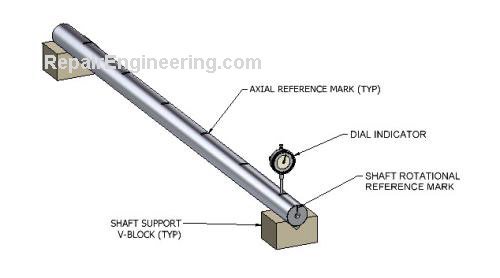
Procedure:
- Support the shaft so that it can be rotated freely. To do this, the shaft can be supported using V-blocks as shown in Figure 2, or supported between centers in a lathe. In some instances, the shaft can be rotated in place in its machine housing supported by its journal bearings.
- Using a felt-tip marking pen, make a "Rotational Reference Mark" on the shaft as shown in Figure 2. The position and orientation of the marking is arbitrary, but once established, the same mark is used throughout the shaft straightening process.
- Create several evenly spaced "Axial Reference Marks" on the shaft using the felt tip pen. The number of axial markings, and their spacing distance, is not critical, and can vary depending on the length and diameter of the shaft. The axial reference marks are used throughout the process.
- Position a dial indicator over one of the axial reference marks as shown in Figure 2. Starting with the Rotational Reference Mark at the 12:00 orientation, slowly rotate the shaft. As the shaft rotates, observe the full range of travel measured by the dial indicator - also known as the Total Indicator Reading (TIR). For purposes of consistency, it is generally helpful to record the amount of the shaft deflection, which is one-half of the TIR value obtained. For example, if the Total Indicator Reading (TIR) is .004 in (0.1 mm), the shaft deflection recorded value is .002 in (0.05 mm).
- With the dial indicator positioned as described in the previous step, note the orientation of the Rotational Reference Mark that corresponds with the "high" point of shaft deflection measured by the dial indicator. For example, if the dial indicator shows that its maximum deflection occurs as the Rotational Reference Mark is at the 3:00 orientation, record the 3:00 position on the survey map.
- Repeat the above steps at each of the Axial Reference Mark locations on the shaft so that a value for deflection and orientation is recorded for each location.
- Review the survey map to determine if there is a trend in the data. Whether the shaft has a twist, a gradual bend, a simple bend at a single location, or perhaps more than one bend, the survey map data should help to identify the type of bend present in the shaft.
- Determine a location to perform a bent shaft straightening correction. The best location is typically the single point on the shaft where the greatest deflection occurs, and may not be at one of the locations previously recorded. By reviewing the survey map, move the dial indicator to axial locations where the data trend suggests that the greatest deflection may occur. By trial-and-error, locate the spot of greatest deflection and mark it.
Regardless of how the shaft is supported, it is important that the dial indicator readings are consistent and repeatable.
It is good practice to update the survey map throughout the straightening process, particularly on difficult projects with multiple bends to be corrected.
When the repair is completed, it is valuable to create one last survey map to serve as the final inspection report of shaft straightness.
In the set-up shown in Figure 2, the dial indicator is positioned very close to the shaft support V-block. What is the purpose of taking a reading at that point? Shouldn't the runout measured near a shaft support always measure zero?
Yes, it should measure zero at that point. The purpose of taking readings near the shaft support is to verify that it is zero. If runout is measured at that location, it is likely due to irregularities in the shaft support, or roundness of the shaft itself, and not due to bending. This applies whether the shaft is supported in V-blocks, between centers in a lathe, or by some other bearing arrangement.
Any shaft support runout issues need to be resolved before proceeding to create the Survey Map. Otherwise, those errors will distort the mapping data obtained.
In the set-up shown in Figure 2, won't gravity cause the shaft to sag in the middle? Will the sag affect the Survey Map data?
Yes, the shaft will sag when supported as shown. However, if the shaft is of uniform cross-section, the sag should be consistent as it is rotated during the survey mapping process. If that is the case, sag due to the effect of gravity can be ignored for purposes of creating the Survey Map.
Bent Shaft Straightening Methods
What are some typical bent shaft straightening methods? There are several, including...
- Mechanical Shaft Straightening
- Spot Heat Shaft Straightening
- Peening Shaft Straightening
- Opposed Heating and Cooling Shaft Straightening
Mechanical Shaft Straightening Method
What is the Mechanical Shaft Straightening repair procedure, also known as "Cold Shaft Straightening"?
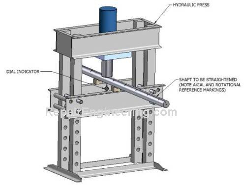
Procedure:
- Create a Bent Shaft Survey Map to determine the location and amount of bend correction required.
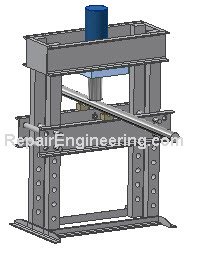
- Install the bent shaft in a suitable press as shown in Figure 3. Rotate the shaft so that the "high side" of the bend with the greatest magnitude of deflection is positioned directly under the ram of the press. Mount a dial indicator as shown in Figure 3 to monitor shaft deflection.
- Slowly actuate the press to apply a force to the shaft while monitoring the amount of deflection on the dial indicator. To get a feel for the responsiveness of the shaft to bend correction, it is a good practice to work in increments and then back-off the press to observe the result.
- Repeat the process until the desired shaft straightness is obtained.
There is typically a material "springback" that occurs as the press is retracted. By trial-and-error, it is possible to determine the amount of over-correction that is needed to reverse the bending in the shaft.
What are the advantages and disadvantages of the mechanical shaft straightening method? Advantages:
- Of all the shaft straightening processes, the mechanical method comes closer to correcting the root cause of the problem for many applications. For this reason, the mechanical method is often considered the first choice approach.
- With a proper set-up, the repair cycle of the mechanical method can be performed relatively quickly. The results can be monitored easily and directly throughout the process by observing the dial indicator reading. For a given shaft, the amount of required correction is relatively consistent and repeatable.
- Because the mechanical shaft straightening method does not require the use of heat, it can be used on a wider range of shaft materials than the spot-heating process.
- The mechanical shaft straightening method requires a press of adequate capacity to correct the bending in the shaft. For large shafts, the availability of a suitable press and material handling equipment can be a limitation. For these same reasons, this process can be difficult to perform while the shaft is in-place.
Spot Heat Shaft Straightening Method
What is the procedure to straighten a bent shaft using the Spot Heating method?
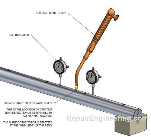
Procedure:
- Create a Bent Shaft Survey Map to determine the location and amount of bend correction required. Rotate the shaft so that the "high side" of the bend with the greatest magnitude faces upward as shown in Figure 4. Part of the success of the spot heat shaft straightening method relies on the weight of the shaft itself to assist in correcting the bend.
- Position dial indicators adjacent to the bend location as shown in Figure 4. If the shaft is supported between centers in a lathe, relax the center preload slightly so that the shaft can flex during the shaft straightening process without binding.
- Working quickly, heat an area of the shaft about .5 in - 1 in. (12mm-25mm) diameter using the welding tip of an oxy-acetylene torch. The objective is to achieve a temperature differential, or local hot spot, between the area being heated and the surrounding area. Therefore, apply the heat evenly and steadily while monitoring the dial indicators.
It is really important to watch the dial indicators during the entire heating process as things will happen quickly, usually within several seconds.
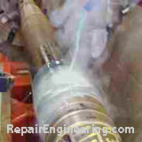
As the shaft is heated, the dial indicators will climb - indicating that the amount of the bend is increasing, temporarily. This is the desired result, even though it seems counter-intuitive. - When the dial indicators show that the desired deflection is achieved, remove the heat and allow the shaft to cool. To speed-up the process, the cooling cycle can be accelerated by various methods such as pouring water on the shaft, or by the use of compressed air, a spray mist system, or by simply using a wet sponge or wet cloths.
If the shaft is straightened in a machine with a water-based flood coolant system, that can also be used to cool the shaft as shown here.
As the shaft is cooled, the dial indicators will move in the opposite direction as they did during the heating process. Continue cooling until the area that was heated is the same temperature as the rest of the shaft. - After the cooling is complete, measure the magnitude of the bend that now exists in the area that was just straightened. Compare this new value with the previous bend deflection prior to the repair.
If no improvement in the bend is measured after the first repair cycle, repeat the spot heating process by increasing the heat-induced deflection in small increments of .010-.020 in (.25-.50 mm) more than used in the previous attempt.
NOTE: At any point, if the amount of heat required causes the shaft to become dull cherry red in color without having an effect on correcting the bend, the spot heating approach in unsuited as a repair method for that particular shaft and an alternate process needs to be used.
- Repeat the process until the desired shaft straightness is obtained.
It is important to get a initial feel for the responsiveness of the shaft to bend reversal. During the first spot heating cycle, heat the shaft until the dial indicators show a thermal-caused deflection of three times the orginal bend.
Using the results from the first shaft straightening cycle, adjust the actual amount of indicated thermal deflection required on subsequent straightening cycles.
If this seems to be more art than science... it is.
Spot heating shaft straightening involves careful observation and educated trial-and error. However, it is generally possible to achieve good results by a methodical application of the process.
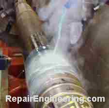 Photo courtesy of Machinist's Inc.
NOTE: Be sure to allow the shaft to cool completely prior to making measurements or further corrections because it will continue to move throughout the cool-down process.
How does the spot heat shaft straightening process work, in principle?
Experienced welders are familiar with metal distortion, known as "drawing" or "heat affected zone", that occurs during the welding process. Spot heat shaft straightening uses the same principle. The mechanics of the process are as follows:
- A small area is heated quickly so that the material in the localized area is in a softened, semi-plastic state while the surrounding material remains relatively cool and solid.
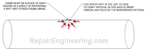
- The spot-heated material expands as it is heated. Because the locally heated area is surrounded by solid (cooler) shaft material, the thermal expansion causes growth in the only unrestrained space available... toward the surface of the shaft. This expansion creates the raised bump on the surface of the shaft that is characteristic of the process.
- As the shaft is cooled, it would be natural to assume that the material in the raised bump would return to its original state prior to heating. In actuality, the exposed surface of the bump cools the most quickly - and becomes solidified in the raised condition.
- The very center of the heated spot is the last to cool and, as it cools, the material contracts. At this stage of the process, the center spot is surrounded on all sides by material that is in a cooler, solidified condition.
- The contraction of the center creates a tensile stress at that location that is very close to the yield point of the material. The localized tensile stress exerts a force that pulls on the surrounding material and causes the shaft to deflect.
In Figure 5, the red lines indicate the shaft forces generated as a result of the localized area of tension. When performed properly, in the correct location, the tension forces can pull the shaft toward straightness.
What are the advantages and disadvantages of the Spot Heat bent shaft straightening method? Advantages:
- The method uses readily available industrial repair shop equipment.
- If necessary, the process can be performed in-place where the shaft is located, whether installed in the equipment in which it operates or in a machine tool such as a lathe.
- The process creates high material stresses in concentrated areas. The stresses can relax over time and affect the straightness of the shaft.
- Spot heating can create a heat-affected zone that is undesirable in critial application shafting. The tendency of creating localized hard spots or stress cracks limits the shaft materials that are suited for this process.
- Spot heating creates a slightly raised bump in the shaft material in the area that was heated. The bump needs to be carefully removed prior to using the shaft, particularly if located in the area of a bearing or seal surface.
- The process can be very time-consuming. After each heating cycle, the shaft needs to be completely cooled to a uniform temperature prior to assessing results.
- There is not a precise method of determining the amount of heating required. The amount of heat needed for each project is best determined by trial-and-error. Several iterations are typically required to achieve the desired result.
Return to top
Impeller
Repair Project
 Impeller Repair
